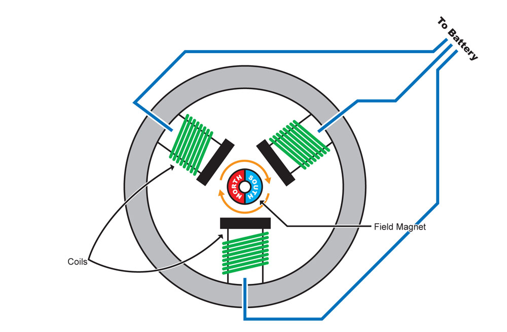
Electric Motor Brushes Wiring Diagram. A dc motor is defined as a device that converts direct current electrical energy into mechanical energy. some common components that may be shown in an electric motor wiring diagram include the motor’s stator, rotor, armature, field coils, brushes, and various. brushed dc motors consist of four key components; The stationary magnet (called a stator), the rotor, the commutator and the brushes (see figure 1). the basic parts of a brushed dc motor are: Brushes and terminals or leads. Understand the different components and their connections for proper installation. The stator is the stationary part with field windings, and the rotor is the rotating part causing mechanical motion. For installing the brushes, you will need a simple strong thin metallic wire as shown in the picture. the schematic diagram of an electric motor typically includes components such as a rotor, stator, commutator, brushes, and a power. Case, bearing and stator magnets (stator, i.e. Stationary), motor shaft and washers, armature / rotor, commutator (and sometimes a varistor), and;
from enginelistjrcamerlingo.z14.web.core.windows.net
The stationary magnet (called a stator), the rotor, the commutator and the brushes (see figure 1). some common components that may be shown in an electric motor wiring diagram include the motor’s stator, rotor, armature, field coils, brushes, and various. Case, bearing and stator magnets (stator, i.e. the schematic diagram of an electric motor typically includes components such as a rotor, stator, commutator, brushes, and a power. Brushes and terminals or leads. A dc motor is defined as a device that converts direct current electrical energy into mechanical energy. Understand the different components and their connections for proper installation. For installing the brushes, you will need a simple strong thin metallic wire as shown in the picture. the basic parts of a brushed dc motor are: Stationary), motor shaft and washers, armature / rotor, commutator (and sometimes a varistor), and;
Electric Motor Brush Wiring
Electric Motor Brushes Wiring Diagram Stationary), motor shaft and washers, armature / rotor, commutator (and sometimes a varistor), and; brushed dc motors consist of four key components; Understand the different components and their connections for proper installation. Brushes and terminals or leads. The stator is the stationary part with field windings, and the rotor is the rotating part causing mechanical motion. the schematic diagram of an electric motor typically includes components such as a rotor, stator, commutator, brushes, and a power. Stationary), motor shaft and washers, armature / rotor, commutator (and sometimes a varistor), and; A dc motor is defined as a device that converts direct current electrical energy into mechanical energy. Case, bearing and stator magnets (stator, i.e. some common components that may be shown in an electric motor wiring diagram include the motor’s stator, rotor, armature, field coils, brushes, and various. the basic parts of a brushed dc motor are: The stationary magnet (called a stator), the rotor, the commutator and the brushes (see figure 1). For installing the brushes, you will need a simple strong thin metallic wire as shown in the picture.